Show Posts

This section allows you to view all posts made by this member. Note that you can only see posts made in areas you currently have access to.


Topics - Cary Austin

Pages: 1 ... 13 14 [15] 16
211
Boosting from an elevated storage tank that is not tall enough, this system increases pressure from 20 PSI to 50 PSI and varies the flow to match the usage.


212
Pumps, Wells, Tanks, Controls / Golf Course old pump with CSV
« on: June 27, 2008, 09:30:44 AM »
Del Norte Golf Course, Cresent City, CA

Really old pump happy with CSV control.  Motor would have to have been replaced to survive the voltage spikes of a VFD.


213
Hi Rob,

Just wanted to let you know, that so far we are very pleased with the cycle
stop valves.  We should have done this years ago.

Thank you again,


Brenda Hammers
Park Tech III - Irrigation Division Manager
Ashland Parks & Recreation
340 S. Pioneer
Ashland, Oregon  97520


214
Autotransformers typically have 3 sets of taps: 50%, 65% and 80%. Motor current is dependent upon the square of the applied voltage, so at 50% taps, the motor current is 25% (.5 x .5) of normal. So if the motor DOL Locked Rotor Current (LRC) is 600% of the Full Load Current (FLC), 1t will be 150% FLC at the 50% taps (600% x 25%). 65% taps come out to 42%, so roughly 250% of FLC, and 80% taps provide 64% current, so 384% FLC. But in the case of an Autotransformer, the LINE current is also reduced by the transformer action, so at 50% taps, the LINE current is 50% of the MOTOR current, so it will be 75% FLC, at 65% it will be 164% FLC and at 80% it will be 307% FLC. This is why Autotransformer starting is sometimes best for reducing the load on power systems (aside from VFDs, which are ultimately the best).

But... that is if the VFD works at all!

Which set of taps is virtually impossible to determine ahead of time; that has to do with the load on the pump. Generally though, most centrifugals will need 65% taps. That is why solid state soft starters are sometimes better for this, they are infinitely adjustable to match the conditions you find in the field. But with a solid state soft starter, your line current and motor current are the same.  So the Auto Transformer will reduce the starting load more than solid state or VFD.

215
Pumps, Wells, Tanks, Controls / Constant Pressure Pump (won't last?)
« on: June 18, 2008, 04:07:23 PM »
Cary Austin
I hate to be the one to say this but, it is not the sediment that will shorten the life of the pump system, it is the variable speed or "constant pressure pump" itself. Over 15 years experience with these has shown me that the average life of all "constant pressure pumps" is less than 4 years. Here is a quote from someone who has seen the problems from a neighbors point of view.

Home Owner #1
"Again, I really appreciate your help and am convinced that a constant pressure mechanical system using a cycle stop valve rather than a VFD system is the way to go especially after understanding how each system works. I think I told you we have friends who are on their third VFD or "constant pressure pump" system in 4 years at the tune of $1100 a crack each time the VFD control panel got zapped."

Home Owner #2
This is very interesting information about the life expectancy of the constant pressure pumps. I had not heard this before. However, it brings a different light on several things that have happened that I thought were disturbingly coincidental.  Within about the first year and one-half after installation of my system, both the original controller and the pump had to be replaced (at different times, but under warranty). My neighbor, who had one of these pumps (smaller hp) put in a new well about 6 months after my job, told me a few weeks ago that the same well people had to replace his pump (under warranty). Now, it appears that's not a coincidence after all (but still disturbing).

Cary Austin
Ah ha! So you didn't really enjoy 2.5 years of constant pressure? This is not unusual, it is the norm. If they can get through the warranty period with only one or two free replacements, just think how much they will make off of you when the warranty is over. Every year and a half or so after the warranty, they get to sell you another $1,100.00 controller. I would try to get it warrantied again before the term is over. Then I would insist on using the warranty credit to replace everything with a standard, longer lasting pump.

A Cycle Stop Valve will give you the same "constant pressure" from a standard pump, and will triple the life of the pump system. The average life of a standard submersible pump is 7 years. Using a CSV to deliver "constant pressure" and reduce the cycling will triple the life expectancy to about 20 years. This is why pump manufacturers recommend you use a Variable Speed Pump instead of a Cycle Stop Valve.

Your pump man is probably as reputable as you say, and just hasn't yet realized his part in this scheme. The pump manufactures are ruining the reputation of honest pump installers. They will tell the pump installer that the VFD will make pumps last longer, and enhance their reputation as the smartest pump man in the country. When they start having problems, the manufacturer says they have a "new" controller that will solve the problem. About the second or third "new" controller they use, the installer starts to understand that they have been hoodwinked. By this time the home owner is doubting that the pump installer has any idea what he is doing, and usually finds another pump installer. It had taken the original pump installer many years to attain his reputation and your business, and only a few VFD's to lose all of it. The manufacturer does not care. They know you will call another pump installer and he will try to sell you the latest and greatest of their so called "constant pressure pumps".

Here is a link to a quote from another reputable pump installer. It just takes most installers a few years to come to the same conclusion.

http://www.cyclestopvalves.com/references_4.html

216
Pumps, Wells, Tanks, Controls / (2) 7.5 HP Boosters
« on: June 06, 2008, 11:27:31 AM »
Hi Cary,

                    Wanted to thank you for the advice given over the phone on Wednesday. The decision was made by the customer  to upgrade the pumps, even though I knew the 5hp could of done the job. It was upgraded to 7.5hp. The attached files are pics of the system with two (2) csvs installed. A problem was experienced with one of the valves and was wondering what could of caused such. Both csvs were adjusted to maintain a constant pressure of 60 psi. When the discharge shut off was closed one of the valves gave a run time of 1min 20 secs. The other valve however was only giving 40 secs, what do you think could cause this problem? Hope there’s an easy solution to this and would like to say that the four CSVB32T recently purchased from you guys have been sold (two in the pics). Will be placing an order for more very soon. Await your reply.


Best Regards

Marcus See Wai


217
Pumps, Wells, Tanks, Controls / 3" CSV Happy Customer
« on: June 06, 2008, 11:23:21 AM »
Dear Mr. Austin,
                         The cyclestop valves recently purchased from your
company (3" Model# CSV3B3F) were installed on  Friday 15 Feb. The system was started yesterday and all the necessary adjustments were made. It can be said that these valves were definitely the right choice for the job. They have performed above and beyond expectations. There was some scepticism on how the valves would function as they were never used before, be rest assured all doubt has been eliminated. A tally is being done to ascertain the performance curves of the pumps most commonly used on local jobs, so valves can be ordered as standard stock items. Hats off to you guys this is a wonderful product. Hope to do a lot more business in the future.

Ps: Karen,
       I got the brochures and cds thank you very much. Coincidentally they
were received today.

Best Regards
Marcus See Wai
Technical Sales Manager

218
Pumps, Wells, Tanks, Controls / Fast Food Pump system
« on: June 06, 2008, 11:19:16 AM »
This was sent by a CSV customer.

An opportunity arised to have another valve installed for a client. The pump is capable of doing a maximum head of 70 psi and a maximum volume of 16 gpm. This was installed at a small KFC outlet. The client indicated they lost two motors in the last three years. After investigating it was discovered that the controller used to start and stop the pump had no draw down volume. It's called a flowmatic and it functions on the principle of flow. Once a faucet opens the pump will start then stop once there's no water flow. In a restaurant situation this type of device won't function properly, as demand will change from time to time. Added to which the pump will come every time a faucet is opened. With that being said the new pump installed was fitted with a CSV1 and the technicians are very impressed on how the device functioned. The pressure switch was set to start at 50 psi and stop at 70psi. Once the pressure gauge reaches 65 psi one would see the needle suddenly slow down and crawl it's way to 70 psi. The pump runs for 1 min and 20 secs and this is with a 6 gallon pressure tank. That's unheard of without a CSV. Hats off again to you guys this device really works. Going to try to workout the bugs in the unit installed at the office and will keep you up to date on the progress. The attached files are pics of the installation.
 
Thanks Again
Marcus


219
Pumps, Wells, Tanks, Controls / Nagel Beverage Co. Inc.
« on: June 05, 2008, 08:32:25 AM »
CSV Does the Job at
New Soft Drink Plant
Another recent project that Hydro Logic Inc., a
hydrogeological consulting firm in Boise, Idaho, completed
using a Cycle Stop Valve was a water supply
system for a state-of-the art $31 million soft drink
manufacturing plant that opened in Nampa, Idaho,
in 2007.
A producer of soft drinks and bottled water, the
water supply plant for Nagel Beverage Co. Inc. can
provide water for a multitude of uses, at a constant
pressure. The range of flow rates required varies from
5 gallons per minute to a maximum of 530 gpm and
is regulated by just one CSV.
“It is quite a versatile and clever fixture that can
deliver 5 gpm to 500 gpm at a constant pressure
while protecting the pump motor from cycling, which
shortens pump motor life more than any other operational
circumstance,” says Ed Squires, president of
Hydro Logic.
Nagel Beverage uses two separate water treatment
systems: a nanofiltration system and a reverse
osmosis system. The initial setup required the CSV to
provide the correct pressures for the reverse osmosis
system. The nanofiltration system requires 400 gpm
and the reverse osmosis system 130 gpm. The discharge
pressure of Nagel Beverage’s 6-inch CSV3B
is 62 psi on a 30 hp pump, with the pressure switch
shutoff at 80 psi.
“It’s sort of a batch-and-run operation,” says
Larry Wheeler, Nagel Beverage’s project manager.
“We start out with a rather slow but steady flow in
the 80 to 120 gpm range but, when everything gets
rocking-and-rolling, it’ll jump up over 500 gpm. The
nanofiltration system is designed for future growth
here, and the CSV will allow for this expansion when
it comes. We have had no problems with the CSV,
and coming out of the pump, that’s the first thing
that we go through.”
Squires considered using a variable-frequency
drive unit in this application, but he says its complexity
was an issue.
“VFDs have many, many applications,” Squires
says, “but they are relatively technical and, like other
computerized equipment, there are glitches. Also,
without an across-the-line electrical bypass and a
separate control panel, if the VFD has a problem, you
don’t have any water. With the CSV, this is one less
potential weakness in the system. Given the wide
range of flow requirements for this project, we felt
the CSV was the best fit. It is quiet and takes up very
little space.
Vance Miller, president of Nagel Beverage, admits
he was somewhat skeptical of Squires’ recommendation
to use a CSV at first. Looking back, Miller says,
“I cannot envision a system that could work better
than the CSV.”
Because high quality ground water is its
lifeblood, Nagel Beverage had Squires design and
supervise the drilling, construction, and development
of its supply well and the discharge well head
plumbing. The CSV regulates all of Nagel Beverage’s
varied water demands, including wash-down, recycling,
commercial, and domestic uses.
“This sort of thing doesn’t get a whole lot of
headlines in the company. We deal with issues. This
is a non-issue,” Wheeler says. “I just wish everything
was made that way. We’re living in an age where it
seems like everything is designed with either no
quality control or with planned obsolescence in mind.
This is just a simple piece of equipment that functions
day in and day out without any adjustments or
maintenance.”
NGWA.org Water Well Journal May 2008 21/


220
Pumps, Wells, Tanks, Controls / Low's Ready Mix Plant
« on: June 05, 2008, 08:31:27 AM »
Not to steal a line from one of those cheesy
infomercials on television, but the slogan
for a Cycle Stop Valve could be, “Set it, and
forget it.”
That’s what Low’s Ready Mix Inc., a state-ofthe-
art and newly constructed concrete manufacturing
plant in Caldwell, Idaho, recently found out.
No easy project, Low’s Ready Mix required
instantaneous flow rates of water at a maximum 900
gallons of water per minute when filling concrete
mixers and minimum flows down to 9 gpm to run
the business office when it is not batching concrete.
If that wasn’t difficult enough, the plant required that
this wide range of Low’s be delivered at a constant
pressure.
Hmm. What to do?
Brad Herrick, project manager for Low’s, did
what anyone else would. He asked an expert.
Herrick consulted with Hydro Logic Inc., a hydrogeological
consulting firm in Boise, Idaho.
And the answer?
“We went with Cycle Stop Valves because we had
such a wide range of flow rates. It is difficult to get a
variable-frequency drive that will cover such a wide
range,” says Ed Squires, president of Hydro Logic,
who began using CSVs five years ago.
“The CSV operates throughout the necessary flow
rates. Another reason we specified CSVs is because
the concrete plant has rapidly shutting valves that are
nearly instantaneous. In this new plant, the water
shutoff valves slap shut, a situation that can lead to
water hammer. The CSVs can react more quickly than
a VFD, which can help eliminate water hammer.”
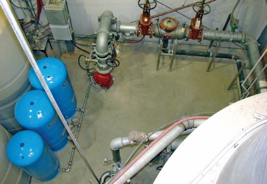
Squires oversaw the installation of an 8-inch
CSV3B for the main water supply well on a 75 hp
pump when the Low’s plant opened in 2006. After a
year of monitoring the plant’s actual water usage
patterns, Squires designed Low’s second (backup)
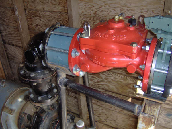
well with two submersible pumps. In this second
well, flows are regulated by a 6-inch CSV3B. This
valve controls the output for both a 3 hp and 75 hp
pump. Both wells are independently functional, but
the second well with two pumps now serves as the
primary well because of its dual pump capability.
The CSV causes the amp draw of the 3 hp to
vary from 4.6 amps to 2.5 amps, and the 75 hp to
vary from 107 amps to 58 amps. This varies the amp
draw of the system from 2.5 amps to 107 amps,
depending on the amount of flow being used at the
time. Many people do not realize that the power consumption
of a pump when controlled with a valve is
very similar to the power consumption of a VFD
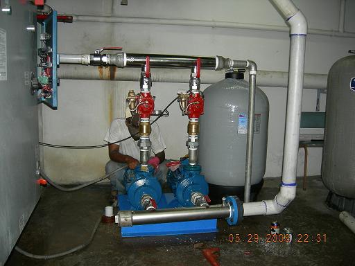
controlled pump. The two-pump setup using the CSV
for control delivers even more energy efficiency and
versatility.
“The CSV really showed its versatility by regulating
a multiple pumping system through a single
valve,” Squires says, “and the manufacturer’s technical
support is beyond compare.”
Another feature of a CSV that is helpful to
Low’s Ready Mix is the part about setting and forgetting
it. The valve’s discharge pressure setting is
adjustable, allowing it to fit the user’s needs. At the
plant, both CSV3B’s have a discharge pressure of
72 psi to 74 psi, with the pressure switch shutoff at
95 psi.
“We find that once the valve is set, it remains
set. That is one of the attributes of these valves,”
Squires says. “They’re very maintenance-free, and if
you do need to adjust them or work on them, all you
need is a crescent wrench. That appeals to a lot of
our clients because most operators like things that
are simple.
“Low’s main focus is making concrete, so they
want a water system that you set and forget. The
CSV, to a large degree, has provided that kind of
system for them.”
No service has been needed for Low’s CSV,
Squires says. He noted the valve’s durability by
recalling another CSV story.
Squires had recommended a CSV for a greenhouse
irrigation well on the outskirts of Boise. The
CSV was installed by one of the client’s employees
and reported it to be “working fine.” Five years later,
Squires and his staff were working on a geothermal
project for the same client and happened to go by the
greenhouse well that had been equipped with the
CSV. However, no CSV was apparent at the well,
which was located in an open field. Nearby, after
looking under a makeshift cover, Squires found the
CSV that had been simply buried in the dirt outside
the wellhead.
“It was still clicking away,” Squires says with a
laugh. “The valve had been working that way since
installation. Now we wouldn’t recommend that,
mind you, but talk about ‘set it and forget it.’”
As for the Low’s project, the only hiccup came
not because of the valve, but rather fist-sized chunks
of concrete that had gotten into the water lines during
installation. Despite the debris, the valve still
worked, but not as smooth as Squires and his staff
thought it should. After checking everything else,
Squires opened up the valve and observed the concrete
chunks had been “beating around” in the valve.
Although there was damage to the epoxy lined
waterways, after the debris was removed, Squires
says “the valve still worked. However, CSV loaned
Low’s another valve to use while they repaired the
epoxy lining in the damaged valve.”
Low’s 3 hp pump will function over flow rates
of 5 to 35 gpm. Once it exceeds that range, the 3 hp
pump kicks off and the 75 hp pump turns on to meet
the increased demand. Low’s can batch 180 cubic
yards an hour on a busy day, dispatching 15 trucks
an hour. Not only that, but the CSV also accommodates
fire-flow requirements of 1100 gpm.
Keeping the Pressure On
Hydrogeological consulting firm designs Cycle Stop Valve controlled pump systems to meet the difficult demands for
a concrete manufacturing plant.
By Mike Price
20/ May 2008 Water Well Journal NGWA.org
An aerial shot of Low’s Ready Mix Inc., a concrete manufacturing plant, in Caldwell, Idaho. Low’s can batch
180 cubic yards an hour.
Mike Price is the Associate Editor
of Water Well Journal. He can be reached
at mprice@ngwa.org
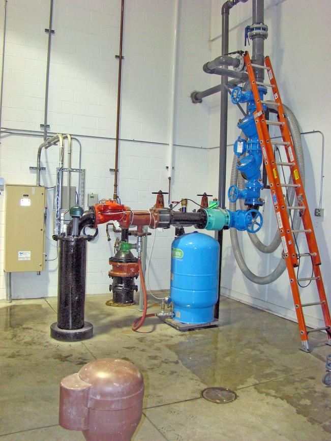
Cycle Stop Valve — 8-inch CSV3B
for backup supply well
Cycle Stop Valve — 6-inch CSV3B
for primary supply well
focus on pumps
“This is just working out great now because
when we need 5 to 600 gpm for a minute or two, the
75 hp clicks on and satisfies that demand, and when
that’s over and it’s slow, and we need to just use 10
to 15 gpm, the 3 hp until we have a big demand
again,” Herrick says. “We’ve got a unique situation
here. I think we’ve got the best of both worlds now.”
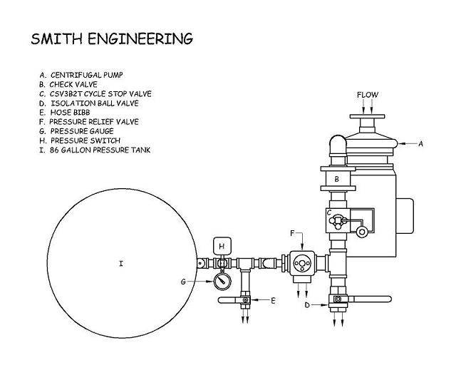
Cycle Stop Valves Inc. of Lubbock, Texas,
received its first of five patents in 1999. Cycle Stop
Valves are pump-control valves that essentially make
variable-flow pumps out of any constant-speed
pumps. The CSV attaches to the discharge plumbing
and automatically regulates the pump’s output to
match the amount of water required by the user.
They give large pumps small-flow capabilities without
the need for huge pressure tanks, water towers,
or complicated electronic devices.
Cycle Stop Valves come in a variety of sizes and
models from 1 to 12 inches. They can handle flow
rates of 1 gpm to 5000 gpm, with pressure adjustments
ranging from 4 psi to 500 psi.
“It’s very non-labor-intensive,” Squires says.
“When it comes to VFDs, most water system operators
defer to hired consultants owing to the technical
difficulties of the computerized systems, programming,
and software learning curves. Don’t get me
wrong, I’m not trying to knock VFDs, because we
have a lot of VFD applications and clients who use
them.
“What I am saying is that I don’t subscribe to the
general misconception that VFDs solve all problems
and work in all situations because they do not.
There’s a place for both of these systems and there
are many good applications suitable to using Cycle
Stop Valves where they actually work better than
VFDs, and generally speaking, simple is better.”
If only everything in life were that simple. WWJ


221
Pumps, Wells, Tanks, Controls / Upthrust Taking out Turbine Bearing
« on: May 18, 2008, 09:16:34 AM »
A question from an email.

what would cause this? Motor thrust upward taking out the bearing. Would assume if anything it would thrust in the downward direction.

222
Pumps, Wells, Tanks, Controls / Pressure Tank Maintenance
« on: May 16, 2008, 12:14:02 PM »
Since this question gets ask so often.  I thought I would start a thread on how to check the air in a pressure tank.

If your pump kicks "on and off rapidly", water pressure in the house is not good, lights in the house "flicker" when water is being used, breaker trips occasionally, or you just want to check the "air pressure in the tank" read the following.

All pressure tanks must have the correct amount of air to water ratio.  The air acts like a spring to push water out of the tank when a tap is opened.  The pressure will decrease as the water is pushed out of the tank, until the pressure drops low enough for the pressure switch to start the pump.  There is usually a 20 pound bandwidth between pump start and pump stop, such as on at 40 PSI and off at 60 PSI.

Once the pump starts at 40 PSI, the tank is refilled and the air in the tank is again compressed until the pressure reaches 60 PSI and the pump shuts off.  The amount of water that the tank will express as the pressure lowers from 60 to 40 PSI, is called "draw down".  Most of the volume of a pressure tank is filled with air.  An 80 gallon size tank only holds 23 gallons of water, and a 20 gallon size tank only holds 5.35 gallons of water.  

There are basically two types of pressure tanks, which are "Hydro Pneumatic" and "Bladder or Captive Air tanks."

223
Pumps, Wells, Tanks, Controls / VFD's are Costing Too Much!
« on: May 13, 2008, 11:52:44 AM »
Email from a Idaho Farmer

Sir,

I am a corporate farm manager in SE Idaho.  We have irrigation systems that use surface water (from a canal) which is pressurized ( at 40 to 80 PSI) for use in sprinkling systems ( Pivot, wheel line, hand line) usually at high volumes ( 1000 to 3000 gallons per minute) but with great fluctuations in flow demand.  We have been using Vfd controlled pumps (centrifugal and one turbine) to meet our needs.  Currently I have one Vfd that needs to be replaced, ( third time in 5 years ( I've spent thousands and thousands of $ trying to keep this one running!)) and I'm now looking at another 2 figure repair/ replace project.  On top of this, the power company now tells me that we need to filter the Vfd s that we have to keep the local pivots with corner units (RF cable guided) from driving off course.  This filtering would also be another 2 figure project.  

I perused your web sight and although I did not see any application that was the same as how I would envision using a cycle stop valve, there are enough similarities that I would like to consider the possibility of ditching the Vfd s and finding a more reliable and cost effective solution.


Farm Manager

224
Pumps, Wells, Tanks, Controls / Motor Bearing Problem from VFD
« on: May 13, 2008, 11:31:23 AM »
Question ask by a VFD customer.

I will start by stating I'm not a motor guy, I'm a water well contractor. The problem that I have run into is that I installed a all new vertical water lube turbine with a vertical hollow shaft motor, in a new well and new controls. This is a 150 hp 460 volt U.S. motor and Abb acs550 series drive. The pump runs as smooth as silk (no vibration)The pump load in under the bearing rating, and I can fine nothing wrong with the system.

The problem is that twice in the last six months the top bearing has start make horible noised and has had to be replaced under U.S. warranty. The motor shop is telling me that the cause of the bearing failure is "shaft current problems" caused be the relationship between the drive and motor. First, does this make sense? Also can some direct me to some reference material that is specific to hollow shaft motors? Finally, any ideas on preventing this in the future? Thanks for your help in advance.

225
Pumps, Wells, Tanks, Controls / VFD's and Radio Interference
« on: December 10, 2007, 09:50:35 AM »
It has long been known that "stray voltage" or "Radio Frequency Interference" or RFI from Variable Frequency Drives or VFD's, can cause problems with other devices in the area.  Television signals can be affected, cell phones, cordless phones, cordless mice, as well as AM and Ham radio's can all suffer from RFI generated from VFD controls.  Here are two links where RFI from VFD's are discussed at length.

http://www.eham.net/forums/RFI/1622   or see text below on second post.

http://www.eng-tips.com/viewthread.cfm?qid=203504&page=2  or see text below on third post.


According to these experts, there are several band aids that can reduce the amount of RFI but, RFI from VFD's cannot be eliminated.  The only way to avoid RFI all together is to control pump systems with something other than VFD control.

Pages: 1 ... 13 14 [15] 16