Show Posts

This section allows you to view all posts made by this member. Note that you can only see posts made in areas you currently have access to.


Messages - Cary Austin

Pages: 1 ... 97 98 [99] 100 101 ... 106
1471
7.5 HP booster


1472
Pumps, Wells, Tanks, Controls / Heat Pump Supply with 2 pumps
« on: August 13, 2009, 02:22:33 PM »
To cut pumping cost for a heat pump, a two pump system is recommended.  I would use a 25S10-7 pump end, with a 1 HP motor.  This pump would deliver 27 GPM at 100' of lift.  Control this well pump with a 20 PSI Cycle Stop Valve, a small pressure tank, and a 10/30 pressure switch.  After the pressure tank, one line tees off to the heat pump, another tees off to a booster pump for the house.  Use about a 3/4 HP jet pump with it's own Cycle Stop Valve set at 50 PSI, and a 40/60 pressure switch.

When the heat pump alone is running, an electric discharge valve opens, the pressure tank drains to 10 PSI, and the pump starts.  The 20 PSI CSV will vary the flow to match a single 10 GPM heat pump, two 10 GPM heat pumps, or two 10 GPM heat pumps while still providing up to 10 GPM for the house, which a total of 30 GPM.  This should cut your pumping cost by more than 1/2 of what a single 2 HP pump can do.  When the heat pump shuts off, the electric discharge valve closes, and the CSV slowly fills the pressure tank to 30 PSI, and the well pump is shut off.

When the house alone is using water, the pressure will drop from 60 to 40 PSI and the 3/4 HP jet pump will start.  The 50 PSI CSV will maintain 50 PSI to the house no mater the flow rate being used.  This jet pump system is drawing water from the well pump system, so the pressure tank on the well pump system empties as the pressure drops from 30 to 10 PSI, and the well pump is started.  The CSV on the well pump feeds exactly as much water to the jet pump booster as the house is using.  Both pumps run as long as the house is using water.  When the house stops using water, the CSV on the jet pump will slowly fill the pressure tank to 60 PSI, and the jet pump is shut off.  Then the CSV on the well pump will slowly fill it's pressure tank to 30 PSI, and the well pump is shut off.

When the heat pump(s) is/are running, the well pump/CSV is delivering 10 or 20 GPM at 20 PSI.  If the house needs water at the same time, the jet booster pump comes on, and the CSV on the well pump opens up to supply both the heat pump and the jet booster pump.  With a 100' pumping level, you should be able to get 30 GPM total when the house and both heat pumps need water at the same time.  When the house no longer needs water, the jet pump system will fill it's pressure tank to 60 PSI, and the jet pump is shut off.  Then the CSV on the well pump reduces the flow to 10 or 20 GPM, matching the amount used by the heat pump(s).  Again, when both heat pumps are shut off, the well pump fills it's pressure tank to 30 PSI, and both pumps stay shut off until water is needed again.

Reducing the main well pump from a 2 HP to a 1 HP will cut the pumping cost considerably.  The only time both pump will run at the same time is when water is being used in the house.  The house will use very little water compared to the heat pumps, so the added electric for the booster pump won't add up to much.  If the system is also used for irrigation about 500 hours a year, both pumps will run this amount of time.

The 2 HP single pump system with CSV described earlier will use $942.00 per year, or $78.50 per month.
The 2 HP single pump system with VFD described earlier will use $751.00 per year, or $62.58 per month.
The 2 pump system with CSV control described here will use $631.00 per year, or $52.58 per
 month.

The 2 pump system will save considerable energy over a single pump system at low flow and high flow conditions.  Using CSV controls, these pumps should last a long time, which is what really saves the most energy.


1473
Pumps, Wells, Tanks, Controls / Heat Pump Supply, VFD vrs CSV
« on: August 13, 2009, 02:18:00 PM »
A two stage heat pump needs 10 GPM for each stage plu another 10 GPM for the house supply.  The heat pump will run on stage 1 at 10 GPM for 4,000 hours per year.  It will run on stage 2 at 20 GPM for 2,000 hours per year.  Then we figure stage 2 at 20 GPM and the house requiring another 10 GPM for a total of 30 GPM running 500 hours a year.  The well is 100' to pumping level and the house requires 60 PSI.  

Figuring a one pump system to handle multiple demands.  I cannot get efficiency curves for 4" submersible pumps.  I would like to post a curve below by Grundfos Pump Company that they made to explain the differences between VFD and CSV.  They used  a 10 HP pump at 231' of head.  We can use this curve to figure the difference of power in percentage, and scale down to a 2 HP, which is what it would take for the system you describe.

Using CSV;
This curve shows 10 HP required for 105 GPM at 231' at 3450 RPM.
At 2/3rds flow       8 HP required for 70 GPM at 231' at 3450 RPM.
At 1/3rd flow         5 HP required for 35 GPM at 231' at 3450 RPM

Using VFD;
At full flow       10.5 HP required for 105 GPM at 231' at 3450 RPM.
At 2/3rds flow    7.7 HP required for   70 GPM at 231' at 3163 RPM.
At 1/3rd flow         3 HP required for  35 GPM at 231' at 2886 RPM.

Full Flow;  
CSV 100% of HP
VFD 105% of HP

2/3rds flow;
CSV  80% of HP
VFD  77% of HP

1/3rd flow;
CSV 50% of HP
VFD 30% of HP

Using a 2 HP submersible to produce 1/3rd flow of 10 GPM for 4,000 hours at .10 per KW.
CSV                  $459.00
VFD                  $276.00
Difference of     $183.00

2 HP submersible to produce 2/3rds flow of 20 GPM for 2,000 hours at .10 per KW.
CSV                  $368.00
VFD                  $354.00
Difference of     $  14.00

2 HP submersible to produce full flow of 30 GPM for 500 hours at .10 per KW.
CSV                  $115.00
VFD                  $121.00
Difference of      $  -6.00

Total difference of $191.00 per year or $15.91 per month.  Figuring a VFD for a 2 HP at about $1,000.00, that would be more than a 5 year pay out.  If the VFD last longer than 5 years there are some savings.  If the VFD last less than 5 years, you never break even.

The CSV has proven to increase the life of pump systems.
The VFD has proven to shorten the life of pump systems.

I got the cost per KW form this web site;

http://www.productiveenergy.com/calculator/pump.asp

Which is also where I got this interesting quote.

"Energy savings for your system may be toward the low end of the above range, but don't forget that usually the energy savings are often small compared to production benefits of having a more reliable system. If the potential savings are towards the low end of the scale, you may not be able to afford pricier optimization options like Adjustable Speed Drives."

There are many variables such as hours of operation, percent of flow, price per KW, and cost of equipment.  When the required flow rate is small the majority of the time the VFD does slightly better. When the required flow rate is high most of the time the CSV does better. When the flow rate is low half the time and high the other half, it is a wash between CSV and VFD. The largest savings are usually in making the equipment last the longest.


1474
Pumps, Wells, Tanks, Controls / 12 year test on pump with CSV
« on: August 07, 2009, 04:07:12 PM »
The following pictures are of an impeller/diffuser, and motor thrust bearing from a 2 HP submersible pump. This was an accelerated test to see how Cycle Stop Valves affect pumps and motors. This pump was actually in the well for over 12 years. During that 12 years, we accelerated the work on the system to simulate a pump system with over 30 years of service.

This pump ran for several years at only 1 GPM. It also ran for several years at varied flow rates from 2 to 25 GPM. All of this time it also supplied two houses with a pressure tank than only held 2.5 gallons of water. So it was also allowed to cycle on and off for intermittent demands. In 12 years we did everything we could think of to try and destroy this pump.

The pump was finally removed for inspection and the following was observed. There is absolutely no down thrust, upthrust, or radial damage to the impeller, diffuser, shaft, or bushings in the pump. The thrust bearing in the motor still looks like brand new, and the motor windings tested and looked perfect.

As you can see from these pictures, the wearable parts of the pump and motor still look perfectly new. There are many thousands more pumps that have lasted this long or longer using a CSV. This particular one we watched everyday and subjected it to the worst possible conditions for over 12 years. Anyone who thinks a Cycle Stop Valve can damage a pump or motor in anyway, should look very closely at these pictures.

I should also say that previously the average life of a pump in this test well was less than 2 years. This CSV made this pump last 600% longer than the average, and it would still be working today if I had not just wanted to see what it looked like.


1475
Pumps, Wells, Tanks, Controls / Another Flotronics replaced with CSV
« on: July 28, 2009, 04:56:11 PM »
Another Flotronics VFD pump station had been giving the customer a lot of grief.  It was replaced with a CSV controlled pump station and the customer could not be more happy.


1476
Flotronics variable speed pump station converted to Cycle Stop Valve control.  This pump station is less than 2 years old.  It has burned up 3 motors in this time and now the drive won't work.  The operator said he was constantly having to reset the drive.  One of the outputs on the drive was bad, and the customer was tired of all the problems so they opted to remove the pump station and replace it with a Cycle Stop Valve controlled pump system.  The customer has been very pleased with this decision.


1477
Pumps, Wells, Tanks, Controls / 5 HP Pump Station Special Price
« on: July 27, 2009, 09:51:24 AM »
This 5 HP pump station can easily be converted for suction lift, flooded suction, or pressure boost applications.  It is set up for 240 volt three phase but, can be easily converted to 480 volt three phase.

Completely assembled and tested.

Special Price $5,950.00    SOLD!!

All you add is water and electricity!


1478
Pumps, Wells, Tanks, Controls / Soft Starter Causes Pressure Surge
« on: July 17, 2009, 12:03:24 PM »
This is typical of the problems with soft start or soft stop.  Head is lost or created by the square of the pump speed.  A pump does not produce enough pressure to open the check valve until the RPM is at 80 to 90% of full pump speed.  When a pump is ramped up slowly to full speed, it is only the last couple of seconds that actually produces enough head to move water.  This makes ramping up the pressure a delicate procedure.  First you must determine at what RPM the pump will actually build enough pressure to buck the static head.  Then you must convert this calculated RPM into hertz.  Now you must bring the pump up to this speed very quickly, then slowly ramp up from this speed to the required speed.  The slightest miscalculation of RPM, either to high or too low, or any change in the static pressure, will cause the pressure to surge.  Any delay in producing the flow required after start up, will cause a negative pressure wave, and a subsequent pressure surge.  The same thing happens with a soft stop, only in reverse.

A Cycle Stop Valve has a hydraulic soft start and soft stop.  It starts and stops the pump at 5 GPM, regardless of the static pressure.   This eliminates pressure surges or water hammer, that can't be eliminated with electronic soft start or ramping up of a VFD.  After start up, the CSV quickly opens up to maintain a constant pressure, before a negative pressure wave can accumulate.   Hydraulic soft start and stop are just that.  After all, isn't the fluid what needs to be started or stopped softly, not the motor?

1479
Pumps, Wells, Tanks, Controls / Soft Starter Causes Pressure Surge
« on: July 17, 2009, 11:35:36 AM »
From an Email

Please Help!

At the local WTP they are having a surge problem from one of the high service pumps. The pump is a 1600 GPM pump with a swing check and soft start drive. The other two pumps are 2400 GPM pumps with soft starts and electric check valves. The problem seems to be that the pump ramps to full speed before the check even opens, and when it does the pressure spikes from ~110 psi to +160 psi. The drive is an Allen-Bradley SMC flex and according to the tech support folks it doesnt matter what the ramp time is set to, the drive will ramp the motor to full speed as soon it can, which should be easy to do when the pump isnt moving water. We tried to current limit the motor from the drive. When it was set at 200% FLA the motor quickly ramped up to partial speed but when the contacts closed at the end of the set ramp time it jumped to full speed. I changed the current limit to 300% and it ramped up as it always did - with the surge pressure when the check opened.


1480
Pumps, Wells, Tanks, Controls / ABB "Claims Energy Savings??"
« on: July 17, 2009, 08:35:35 AM »
"Saving energy with variable speed drives by ABB
Traditionally, throttling is used to regulate flows of air or fluid. While throttling reduces the flow, the motor is still running at full speed and works even harder as it has to work against a restriction. By reducing the speed of the motor, the variable speed drive ensures no more energy than necessary is used to achieve the required flow.
This is because the torque needed to run a pump or fan is the square of the volume. For instance, reducing the pump speed to 80% only requires 64% of the torque (0.8x0.8) (Tµn2).

Furthermore, to produce 64% of the torque only requires 51% of the power (0.64x0.8) (Pµn3), as the power requirement is reduced in the same way.

The explanation for this lies in the pressure difference across the impeller. When less pressure is produced, less acceleration of air or fluid across the impeller is required. It is the simultaneous reduction of acceleration and pressure that multiplies the savings."


Does ABB really not understand pumps any better than this?

"Traditionally, throttling is used to regulate flows of air or fluid. While throttling reduces the flow, the motor is still running at full speed and works even harder as it has to work against a restriction."

Anybody who understands centrifugal pumps knows that throttling the discharge flow reduces the work or load on the motor.  In many cases, throttling a pump with a valve will reduce the "work" or power consumption more than varying the speed.  Restricting the flow from a centrifugal pump certainly does not make the pump work harder.  Even restricting the flow from a fan does not make the motor work harder.  This can easily be proven by putting you hand over the outlet of a blow dryer.  You will notice that the motor actually speeds up, because restricting the air flow reduces the load on the motor.


"A centrifugal pump or fan running at half speed consumes only one-eighth of the energy compared to one running at full speed."

While this statement is true, what they are not saying is that reducing the speed of a pump to half speed, also reduces the head produced by 75%.  Therefore, it is impossible to reduce the speed of a pump to 50%, and still produce enough head to function. Even reducing the speed of a pump by only 10%, reduces the head produced by 19%.  Head or pressure is reduced by the square of the pump speed.  Usually a reduction in speed of less than 10% is all that is possible, to still be able to produce enough head or pressure to function at all.

There are so many other good uses for variable speed drives on things like conveyor belts, escalators, even positive displacement pumps, that there should be no reason for such deception about energy savings with centrifugal pumps.  Restricting the flow from a full speed pump does not make the motor work harder.  Simply restricting the flow from a pump with a valve can naturally reduce the energy consumption by as much as 50%.  The fact that it is only possible to reduce the speed of a pump by less than 10%, means that varying the speed can only reduce the energy consumption by 28% or less.

1481
Pumps, Wells, Tanks, Controls / Calculating Minimum Cooling Flows
« on: July 08, 2009, 10:38:02 AM »
Electric motors produce heat.  The heat in motors must be displaced or the heat will build up in the motor and cause a failure.  Most above ground type motors have a fan that blows air through the motor for cooling purposes.  As long as the motor is running at full speed, so is the fan.  Devices such as a Cycle Stop Valve derate the motor without decreasing the RPM.  Derating a motor means that the amperage, load, or heat produced is decreased.  When the heat produced is decreased, and the fan is still spinning at full RPM, the motor runs much cooler and will provide a much longer service life.  With devices such as a VFD, the amperage or heat produced decreases slightly but, the RPM of the motor and attached fan are also decreased.  With slower RPM and a decreased air flow to the motor, heat is not displaced properly, and an auxiliary cooling fan may be needed to prevent premature destruction of the motor.

With submersible motors, the water flowing past the motor before entering the pump, is used to cool the motor.  Just because the motor is submerged under water does not guarantee that the flow will pass by the motor before entering the pump.  When installing the unit in a large body of water, or when installing above perforations or above the water producing zone is not possible, a flow sleeve is mandatory.  Even in situations where the pump is installed above the perforations or water producing zone, a flow sleeve will increase the velocity of flow past the motor.  The flow sleeve should be as small a diameter as possible, to increase the velocity past the motor, without causing much friction loss at high flow rates.  

Minimum flow rates are figured to maintain a certain velocity past the motor.  When running at full service factor load, in water less than 86 degrees, this velocity must be maintained to prevent overheating of the motor.  When the water is hotter than 86 degrees, derating the motor is necessary to prevent overheating.  Derating a 5 HP submersible motor by as little as 25% will prevent overheating, even with water temperature as high as 140 degrees.  In hot water applications, the velocity must also be increased.  However, when the motor load is derated, and the water temp is less than 86 degrees, the velocity past the motor can be decreased.  

Again, devices such as a Cycle Stop Valve derate the motor without decreasing the RPM.  When the motor is derated, and the water temp is less than 86 degrees, very little velocity is needed to maintain adequate cooling for the motor.  For instance, a 6" motor inside an 8" casing or sleeve, pumping water less than 86 degrees, and running at full service factor load, needs 45 GPM minimum to maintain adequate cooling.  This same motor derated with a Cycle Stop Valve, can maintain adequate cooling with as little as 5 GPM flow past the motor.  The cooler the water, and the more derated the load, the lower the minimum flow required to properly cool the motor.  This is why in over 17 years of service, there has never been a single motor destroyed from a proper Cycle Stop Valve installation.

While Cycle Stop Valves derate the motor load and reduces the minimum flow required, a VFD does not derate but, "creates" a smaller motor from a larger one.  When the RPM of a motor/pump is reduced with a VFD, a 20 HP motor may only be pulling a 10 HP load.  However, the harmonic current from the VFD increases the heat in the motor windings.  This requires enough cooling flow to adequately cool a 10 HP motor running at full service factor load.  It takes much more velocity or flow to cool a fully loaded 10 HP motor that was "created" from a 20 HP motor using a VFD, than it does to cool a 20 HP motor that has been derated to a 10 HP load using a Cycle Stop Valve.  This is why a VFD controlled motor still requires as much  minimum flow as a motor running at full service factor load, and a Cycle Stop Valve controlled motor can operate safely at a much lower flow rate.  Many motor and pump companies also sell VFD's, and do not want you to know that motors last longer and minimum flow rates can be much lower with a Cycle Stop Valve system, than with a VFD controlled system.  The "not so minimum flow" required by a VFD system can create many problems when the demand is below a set amount.  With a Cycle Stop Valve controlled system, there is no demand too small to cause overheating of the motor.

Motor companies do not disallow warranties for something that "might" happen to a motor.  When you bring a motor in for a warranty inspection, the motor company has no idea how the motor was being controlled.  Their inspection at that time can easily determine if the motor suffered from a lack of cooling or not.  Damage from lack of cooling is obvious and occurs when the pump is allowed to run dry, pumping against a frozen well head, or a completely plugged pipe line.  Motors can also be destroyed when pumping from a top feeding well without a cooling sleeve in place, or by running at low flow when controlled with a VFD.

Cycle Stop Valves, Inc. has always offered to cover any motor controlled by a properly installed CSV system, if warranty was denied by the motor manufacturer due to lack of cooling.  In more than 17 years with hundreds of thousands of installations, there has never been a single motor destroyed from lack of cooling due to the installation of a Cycle Stop Valve.   Some pump and motor companies continually try to convince you that Cycle Stop Valves will cause motor overheating.  The truth, is that Cycle Stop Valves have repeatedly proven to increase the life of pumps and motors.   Which contrary to what they want you to believe, is exactly why pump and motor manufacturers desperately try to discourage the use of Cycle Stop Valves.

1482
Pumps, Wells, Tanks, Controls / Happy in the Wildwildmidwest
« on: June 15, 2009, 01:07:42 PM »
I love our cycle stop valve!

I added 1000 gallons to our in-ground pool today. Our CSV made that happen in a single continuous (and now totally silent) pump cycle. Our water pressure is perfect for showers and everything else. With a little more adjustment I succeeded in getting our pressure switch to operate at 45-60 PSI. We now have a fully optimized domestic water system.

Thank you so much for your guidance! Your tip about plumbing a flexible hose into our water line was genius. I bought a 7/8" I.D. washing machine hose and plumbed about 3 feet of it above the CSV after cutting out an L-shaped 4 foot section of copper pipe. The hose arches through a gradual 90 degree turn which dissipates vibrations throughout the radius of the arch. Now our well pump is completely silent upstairs. I can hear it in the basement only if I listen very closely. Thank you, thank you, thank you! No more waking everybody up when the pump runs.

I'm a 100% satisfied CSV owner! I've been spreading the word to everyone I know and will continue to do so. Thanks also to everyone here who showed the path to plumbing nirvana.

http://www.terrylove.com/forums/showthread.php?t=28836&page=2

1483
Pumps, Wells, Tanks, Controls / Another happy customer
« on: June 15, 2009, 01:03:41 PM »
Just a little update as I have finished my entire sprinkler system. I can not tell you how awesome this system works. I am off the meter for all of my yard watering. I have been using this for several months now and it works perfect. The cycle stop valve was the hot ticket because I can use my hose bib and not cycle the pump. It is working so well I have planted extra grass. I am doing the whole yard with five stations with Hunter HPV valves and four Hunter I-20 roters to a station. I am using 6 and 8 GPM nozzels and the pump has no trouble keeping up with them at 40 PSI.

The best part, my old water bill was $280.00 or so a month and that was water about 2/3 of the area I am currently watering. My last three water bills ....... $24.32. I will have the system paid for in no time.

Thanks again

1484
Eliminate Water Hammer
                            with
Transient Wave Canceling Technology

Many recent articles have explained the necessity of finding and repairing leaks in water mains.  Leaks in water lines can be anything from tiny stress fractures to blow outs that requires rescues by helicopter.  Either way these leaks waste millions of gallons of our precious fresh water everyday.  Without first addressing the cause of the problem, finding and repairing leaks can be a futile effort.

Corrosion and age of the pipe causes some leaks but, the main cause of leaks in a piping system is  water hammer. Once leaks occur, they act as pressure relief for the water hammer.  Repairing leaks will leave no place for the water hammer to vent, which will cause new leaks to reappear, as fast as the old ones are repaired.  Repairing leaks can be a money pit, if we don't stop the water hammer that caused the leaks in the first place.

Water hammer causes pressure spikes that can be 10 times higher than normal operating pressure.  Transient pressure waves cause water hammer.  Because of the incompressibility of water, transient pressure waves travel through a pipe line at speeds of 3,000 to 8,000 feet per second.  When these supersonic waves hit dead ends, elbows, or tees, they create water hammer.  These waves bounce off of dead ends, elbows, and tees and can ricochet back and forth many times before subsiding.  A single wave can cause many water hammer events, which is the main cause of destruction for pipe and fittings.

Transient pressure waves and the subsequent water hammer can be created on the demand or the supply side of the system.  On the demand side, slow opening and slow closing valves should be employed, and water hammer arresters should be installed at strategic locations.  However the majority of water hammer problems are created on the supply side of the system.  Most water hammer problems occur as pumps are started and stopped to allow water towers and hydro pneumatic tanks to fill and drain, or when pump control systems react too fast or too slowly.
 
When a pump is started, a transient pressure wave is created that travels throughout the entire plumbing system.  When a pump is stopped, the water continues to travel or stretch forward, which creates a negative pressure.  The water then snaps back like a rubber band, which instantly changes the negative pressure to a spike of positive pressure.

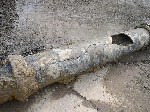
These swings from negative to positive pressures contract and expand the pipe line, and water hammer repetitively pounds away at the pipe, fittings, and thrust blocks.  In the worst cases, elbows, tees, pipe, and valves can be blown off completely and major leaks spring up like geysers.  At the very least, tiny stress fractures and small cracks appear in thousands of places in the pipe system.  Either way millions of gallons of water is lost through breaks and leaks, while at the same time, negative pressure waves can draw contaminants into the pipe line.

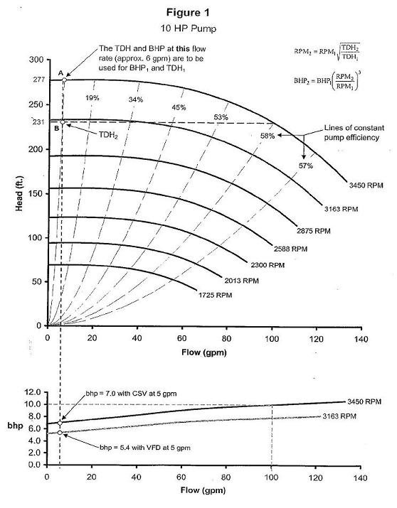
One of the first rules we learn in life, is that a body in motion wants to stay in motion, and a body at rest wants to stay at rest.  Water in a pipe line takes this law of physics to the extreme.  It should stand to reason that keeping a pump running continuously, should help eliminate transients and water hammer, verses starting and stopping the pump numerous times.  To keep the pump running continuously, Pump Control Valves, Variable Frequency Drives (VFD's), or other devices must vary the flow rate of a pump to match the usage.  However, the slightest delay in response from slow opening and slow closing valves, VFD's, and soft starters can actually cause transient waves, as much or more than too fast of a response.  Delayed reactions can even accentuate and  perpetuate transients and water hammer, making matters worse.

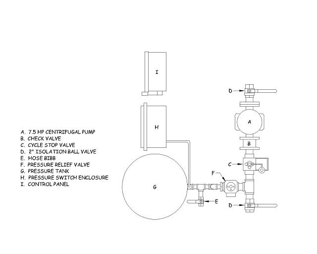
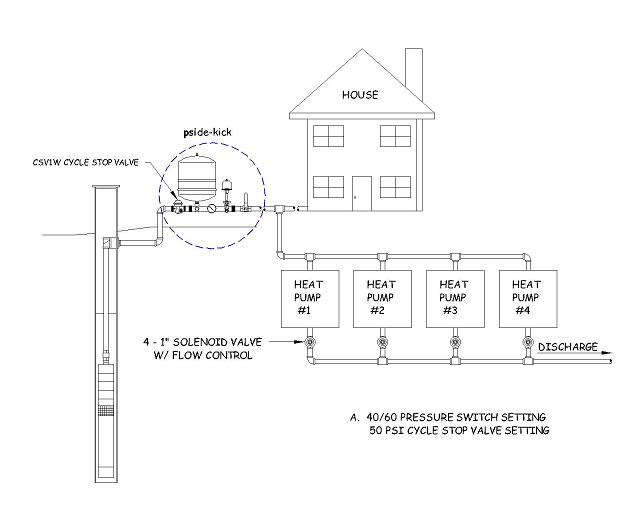
Cycle Stop Valves or CSV's offer a simple solution to the problem.  CSV's are designed to vary the flow from the pump to match the usage, which keeps a pump running  constantly.  Working on a pressure reducing principal, they continually regulate the flow from the pump by maintaining a constant pressure.  This design never allows the valve to completely close against the seat.  Never completely closing, and not having to pop open from a closed position, eliminates "hunting" or pulsing of the pressure, that is known to fully closing type valves.
  
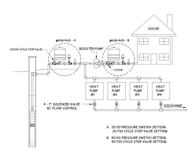
Because they never completely close, the valve travel or reaction speed of the CSV can be increased exponentially, allowing extremely fast reactions to any changes in system pressure.  This cancels out transient pressure waves much the same way as noise canceling technology cancels out noise.  When an increase in system pressure is sensed, these valves instantly decrease the flow rate of the pump.  Likewise when they sense a decrease in system pressure, these valves instantly increase the flow from the pump.  When a negative pressure wave is instantly met with positive pressure, and positive pressure wave is instantly met with reduced pressure, transient waves are cancelled out.

Slow opening and slow closing pump control valves, even other so called "Constant Pressure Valves", can actually cause transient pressure waves.  Slow opening of a control valve will cause the pressure to pulse, starting a transient wave, no matter how slow the control valve is opened.  Closing a control valve before the pump is shut off, will cause a negative pressure wave, no matter how slow the valve is closed.

Soft starting and stopping of the pump can cause the same transient waves as slow opening and slow closing control valves.  When a large demand is opened, waiting on a soft start or slow opening valve can further accentuate transient pressure waves and water hammer.  When a large demand is closed, waiting even a fraction of a second on a soft stop or a slow closing control valve, can cause tremendous spikes in pressure.

Variable Frequency Drives or VFD's can also be programmed to maintain a constant pressure.  A VFD system can be programmed to respond very fast.  However, a VFD is usually programmed to adjust the pumps speed only every 3 to 5 seconds, or even longer.  The quicker the response time programmed into the VFD, the more "hunting" or bouncing of pressure is seen and felt.  Even if a VFD is programmed to respond quickly, it takes a fraction of a second for the transducer to see the pressure change, send a signal to the controller, and for the controller to change the speed of the motor/pump.  By this time the transient wave, moving at thousands of feet per second, has already bounced off and is causing more destruction several thousand feet down the pipe line.

Programming a delay into a VFD or standard pump control valve, is much like swinging at a baseball, after the ball is already hit the catcher's mitt.  The effort is too little and too late.   Increasing the speed of a VFD or standard pump control valve will cause "hunting" and pulsing of the pressure.  Even if it were possible for them to operate very fast, the reaction time would be just a bit off.  Even the slightest bit off, is like landing on a trampoline a split second after someone else.  It causes a catastrophic collision and shoots the person (pressure) extremely high.

Transient pressure waves cause water hammer.  Water hammer causes pipe line breaks.  Pipe line breaks are time consuming, expensive to repair, waste millions of gallons of our precious fresh water everyday, and allow contamination to enter our clean water supplies.   It is a futile effort, and a waste of time and money, to repair any leaks before the root cause of the problem has been identified and corrected.  

Wasting water is simply unacceptable.  There is a solution.  Cycle Stop Valves are the only pump control with transient wave canceling technology.   Cycle Stop Valves have proven to eliminate water hammer and line breaks in numerous water systems, large or small.   Don't fix another leak without first solving the problem that caused it in the first place.  Every water pump system needs the wave canceling technology of a Cycle Stop Valve.


1485
The spring is so short in those CSV1W's that you don't have much adjustment.  It should be able to go down to about 45 PSI but, if it is holding 58 at low flow, I wouldn't change a thing.

Pages: 1 ... 97 98 [99] 100 101 ... 106