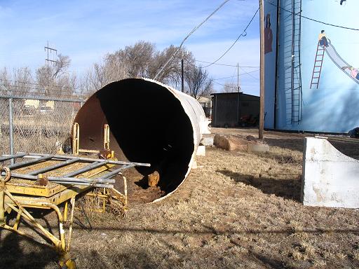
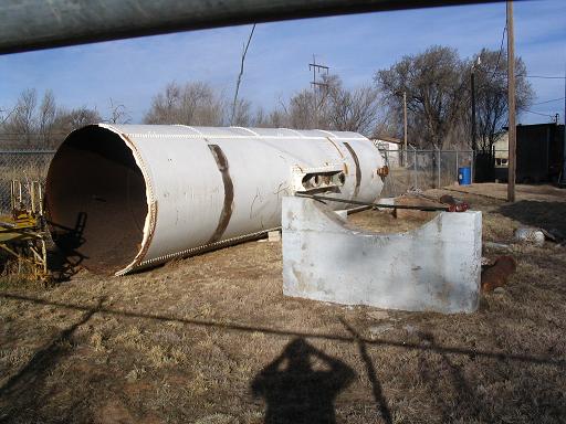
Show Posts

This section allows you to view all posts made by this member. Note that you can only see posts made in areas you currently have access to.


Messages - Cary Austin

Pages: 1 ... 99 100 [101] 102 103 104
1501
Pumps, Wells, Tanks, Controls / Constant Pressure Pump (won't last?)
« on: June 19, 2008, 09:13:49 AM »
Response;

OK, a Sub Drive 150 runs a 3 HP motor and usually has a 1.5 HP pump end.  So you might call it a 3 X 1.5.   The controller speeds up the motor from the standard 3450 RPM to about 4700 RPM, so they can use a 1.5 HP pump and get 3 HP performance.  Increasing the speed of the pump is one problem with these type pumps, because every time you double the RPM, the pump wears out 4 times faster.   So pumps will not last as long spinning 4700 RPM as they do when spinning the standard 3450 RPM.

The next problem with the Sub Drive or Mono Drive is the little switch.  This system never sets the speed of the pump as needed.  The little switch basically starts and stops the pump rapidly and continuously to match the flow being used.  The switch makes it work much faster and eliminates some of the problems associated with "pressure transducers" that are used on nearly every other brand of variable speed pump.  The problem is that this switch makes and brakes about 2,000,000 times per month.  Nothing can survive two million changes of state per month.  About three months of continuous use and the switch is toast.  So if you only use your pump for an average of 4 hours per day, then every 18 months this switch, controller, or both are going to fail.

Another problem is the controller itself.  I will bet your first controller was painted black.  Then the replacement or "new" controller was painted white, supposedly to keep it cooler.  These controllers produce and waste a lot of heat.  The heat will destroy them.  They are only rated to 50C ro 122 F temperature, and almost any well house will get this hot in the summer.  Especially when the controller and it's fan are adding more heat inside the pump house.  The lint and dirt that is drawn in by the cooling fan also increase the heat and shortens the life of the controller.  Ever seen how much dirt collects in a computer sitting in your study for a couple of years?  This is nothing compared to the dirt the controller picks up out in the garage or well house.  Even the "new" white controllers are turning black, and making the wall they are mounted on turn black.

A better analogy of the difference between a so called "constant pressure pump", and a standard pump system using a CSV to produce "Constant Pressure" follows.  When there are two or more ways to accomplish the same task, the simplest way is always the best way.  (See; Occam's Razor)

NASA needed a pen for astronauts to take notes in space.  They needed the pen to work in zero gravity or several G's.  The pen needed to work in absolute vacuum or extremely high pressure.  It needed to work in sub zero temperature or extremely hot temperature.  It had to work right side up or upside down.  Development of this pen cost millions of dollars, and the pens were so sophisticated that each pen cost a million dollars to produce.  The Russians had the same requirements and they discovered that they got better performance at a fraction of the cost, using a #2 lead pencil.  The variable speed pump is the NASA pen, and the CSV is the pencil.  After all, we are just pumping water, a computer just makes it more expensive and less dependable?

If the "skin effect" from the variable speed controller has not caused a hole in the drop pipe, then your sediment issue is a whole other problem.  We use a gravel pack in the well that is almost as small as sand.  This filters out the dirt and doesn't let it enter the well.  However, some sediment is so fine that is floats in the water and even a small gravel pack won't filter it out.  Many times this can be pumped clean but, you have to pump the well hard, then let it recoup, and pump the well hard again.  Sometimes this has to be done numerous times to get out the light sediment.

1502
Pumps, Wells, Tanks, Controls / Constant Pressure Pump (won't last?)
« on: June 19, 2008, 09:12:30 AM »
From the Homeowner;

You are calling it as it happened. Wow. What great insight into this situation. When the controller went out about 6 months after installation, I was informed that the company had a problem with the previous type of controller and so they put out a new one, but I must have gotten one of the old ones by mistake. Hmmm. So, then, I supposedly got one of the genuine "new" ones. They have had to adjust something related to a pressure switch; other than that the controller seems to have worked (so far). Oooof! This does not bode well for this system. I am glad I still have the old well. That Jacuzzi pump is 18 years old. Thanks for this information !!

1503
Pumps, Wells, Tanks, Controls / Constant Pressure Pump (won't last?)
« on: June 18, 2008, 04:07:23 PM »
Cary Austin
I hate to be the one to say this but, it is not the sediment that will shorten the life of the pump system, it is the variable speed or "constant pressure pump" itself. Over 15 years experience with these has shown me that the average life of all "constant pressure pumps" is less than 4 years. Here is a quote from someone who has seen the problems from a neighbors point of view.

Home Owner #1
"Again, I really appreciate your help and am convinced that a constant pressure mechanical system using a cycle stop valve rather than a VFD system is the way to go especially after understanding how each system works. I think I told you we have friends who are on their third VFD or "constant pressure pump" system in 4 years at the tune of $1100 a crack each time the VFD control panel got zapped."

Home Owner #2
This is very interesting information about the life expectancy of the constant pressure pumps. I had not heard this before. However, it brings a different light on several things that have happened that I thought were disturbingly coincidental.  Within about the first year and one-half after installation of my system, both the original controller and the pump had to be replaced (at different times, but under warranty). My neighbor, who had one of these pumps (smaller hp) put in a new well about 6 months after my job, told me a few weeks ago that the same well people had to replace his pump (under warranty). Now, it appears that's not a coincidence after all (but still disturbing).

Cary Austin
Ah ha! So you didn't really enjoy 2.5 years of constant pressure? This is not unusual, it is the norm. If they can get through the warranty period with only one or two free replacements, just think how much they will make off of you when the warranty is over. Every year and a half or so after the warranty, they get to sell you another $1,100.00 controller. I would try to get it warrantied again before the term is over. Then I would insist on using the warranty credit to replace everything with a standard, longer lasting pump.

A Cycle Stop Valve will give you the same "constant pressure" from a standard pump, and will triple the life of the pump system. The average life of a standard submersible pump is 7 years. Using a CSV to deliver "constant pressure" and reduce the cycling will triple the life expectancy to about 20 years. This is why pump manufacturers recommend you use a Variable Speed Pump instead of a Cycle Stop Valve.

Your pump man is probably as reputable as you say, and just hasn't yet realized his part in this scheme. The pump manufactures are ruining the reputation of honest pump installers. They will tell the pump installer that the VFD will make pumps last longer, and enhance their reputation as the smartest pump man in the country. When they start having problems, the manufacturer says they have a "new" controller that will solve the problem. About the second or third "new" controller they use, the installer starts to understand that they have been hoodwinked. By this time the home owner is doubting that the pump installer has any idea what he is doing, and usually finds another pump installer. It had taken the original pump installer many years to attain his reputation and your business, and only a few VFD's to lose all of it. The manufacturer does not care. They know you will call another pump installer and he will try to sell you the latest and greatest of their so called "constant pressure pumps".

Here is a link to a quote from another reputable pump installer. It just takes most installers a few years to come to the same conclusion.

http://www.cyclestopvalves.com/references_4.html

1504
Usually a domestic and fire pump system combined uses two pumps.  A smaller pump that delivers higher pressure is used for the domestic water.  Then a large volume pump is used for fire protection.  The system is usually staged a little different from a regular two pump system using a Cycle Stop Valve.

For example;

Pump #1 is set to come on at 50 and off at 60 PSI.

Fire Pump #2 is set to come on at 40 PSI.  The Cycle Stop for this pump is set at 70 PSI.  And the pressure switch shuts off this pump at 80 PSI.

Anytime pump #1 cannot keep up with the demand, such as when needing fire flow, the pressure drops from 50 to 40 and Pump #2 comes on.  The Cycle Stop Valve on the fire pump brings the pressure up to 70 PSI.  When it goes through 60 PSI pump #1 is shut off.  When there is no more flow required, the CSV lets the pressure go up to 80 and the fire pump is shut off.

When water is again called for, the pressure will drop to 50 PSI, and pump #1 again takes control.

If the system only has one pump, then the pressure settings are adjusted to the fire flow requirements, and a regular pressure reducing valve can be used on the domestic line to control the everyday pressure.

1505
Pumps, Wells, Tanks, Controls / (2) 7.5 HP Boosters
« on: June 06, 2008, 11:33:00 AM »
Hi Marcus

That is a beautiful pump station. Thanks for the pictures. I can’t see where the pressure switch is located but, it doesn’t look like there is enough room at the bottom of the pressure tank to connect the pressure switch. The larger the pumps, the more important it is to have the connection to the pressure switch or switches located as close to the tank as possible. It may even have something to do with the run time.

Run time is not nearly as important with the CSV. I know run time has always been a very important part of properly setting up a pump system. With the CSV, the pump continues to run as long as there is a small demand for water so, run time is really not that important. As long as you have 30 or 45 seconds of run time, you can be sure that the setting of the CSV is lower than the off setting of the pressure switch, and that is really what is important.

Minimum flow through the CSV is actually determined by the differential pressure between the dead head of the pump and the pressure setting of the CSV. When the CSV closes, the little notch in the CSV makes a certain size opening. A little extra or less powder coat, and the stiffness of the diaphragm can change the opening size slightly from one valve to another. This can cause slight differences in the size of the notch opening, which can make run time from one pump to another slightly different.

We like to say that the minimum flow through that size CSV is 5 GPM. However, that is basically an average. The minimum flow can be as little as 1 GPM with a differential pressure of only 10 PSI, or it can be as much as 7 GPM for a pump that delivers 125 PSI differential pressure. I have a chart for this that I can send you on Monday. This will basically automatically adjust the minimum flow to the cooling requirements for the pump. A multistage pump that builds high back pressure needs more cooling than a single stage pump that puts out very little back pressure. So the different minimum flows at different differential pressure works out great.

Depending on the minimum flow created by the differential pressure and the draw down of the tank, run times can vary from system to system. The only thing that is really important is the run and off times when the flow rate is less than the minimum flow. You can use our tank sizing calculator on the web page to give you an idea of the maximum number of cycles per day. With the worst case scenario being a flow rate of about half the minimum flow, you can determine the tank size required to keep the cycles per day less than what is required by the motor and pump manufacturer. Maximum cycles per day is what is important, not so much just run time.

The slightest difference in the pressure setting of the two valves, and a little difference in the thickness of the powder cost over the notch, could easily cause a 40 second difference in run time with such a small tank but, it is not that important.

Normally we set up two pump systems to lead and lag instead of alternating. Alternating wears out both pumps at the same time so you basically do not have a spare pump. Lead lag only runs pump #2 when pump #1 cannot keep up with demand, or if pump #1 stops working. You can use an exercise clock to make sure pump #2 gets used a few minutes once or twice a weak just for exercise, then when a backup or spare pump is needed, it will still be like new instead of being just as worn out as pump #1. In a lead lag set up, pump #2 really does not have ANY run time. This is because the pressure setting of the CSV on pump #1 is what shuts off pump #2. With the CSV, run time is not important because the pump never comes on unless there is enough demand to keep the pump running for a while. Then the pump never goes off unless there is very little or basically no demand. So run time as we used to know it is no more important than the off time. Now run and off time can be figured by using half the minimum flow through the CSV, to determine the required tank draw down. Then again, with the lead lag set up, run and off time is only important for pump #1, as there is really no way to make pump #2 cycle at all.

Also, alternators only switch to the other pump when pump #1 shuts off. When you have a system that is large enough to always have a demand or leaks as much as the minimum flow through the CSV, pump #1 will NEVER shut off, so pump #2 may not ever get the exercise it needs.

The more you use CSV’s, the more ways you will find you can use them, and the less you will worry about run times and other things that used to be so critical.

I hope this helps. Let me know if you have further questions.

Thanks

Cary

1506
Pumps, Wells, Tanks, Controls / (2) 7.5 HP Boosters
« on: June 06, 2008, 11:27:31 AM »
Hi Cary,

                    Wanted to thank you for the advice given over the phone on Wednesday. The decision was made by the customer  to upgrade the pumps, even though I knew the 5hp could of done the job. It was upgraded to 7.5hp. The attached files are pics of the system with two (2) csvs installed. A problem was experienced with one of the valves and was wondering what could of caused such. Both csvs were adjusted to maintain a constant pressure of 60 psi. When the discharge shut off was closed one of the valves gave a run time of 1min 20 secs. The other valve however was only giving 40 secs, what do you think could cause this problem? Hope there’s an easy solution to this and would like to say that the four CSVB32T recently purchased from you guys have been sold (two in the pics). Will be placing an order for more very soon. Await your reply.


Best Regards

Marcus See Wai


1507
Pumps, Wells, Tanks, Controls / 3" CSV Happy Customer
« on: June 06, 2008, 11:23:21 AM »
Dear Mr. Austin,
                         The cyclestop valves recently purchased from your
company (3" Model# CSV3B3F) were installed on  Friday 15 Feb. The system was started yesterday and all the necessary adjustments were made. It can be said that these valves were definitely the right choice for the job. They have performed above and beyond expectations. There was some scepticism on how the valves would function as they were never used before, be rest assured all doubt has been eliminated. A tally is being done to ascertain the performance curves of the pumps most commonly used on local jobs, so valves can be ordered as standard stock items. Hats off to you guys this is a wonderful product. Hope to do a lot more business in the future.

Ps: Karen,
       I got the brochures and cds thank you very much. Coincidentally they
were received today.

Best Regards
Marcus See Wai
Technical Sales Manager

1508
Pumps, Wells, Tanks, Controls / Fast Food Pump system
« on: June 06, 2008, 11:19:16 AM »
This was sent by a CSV customer.

An opportunity arised to have another valve installed for a client. The pump is capable of doing a maximum head of 70 psi and a maximum volume of 16 gpm. This was installed at a small KFC outlet. The client indicated they lost two motors in the last three years. After investigating it was discovered that the controller used to start and stop the pump had no draw down volume. It's called a flowmatic and it functions on the principle of flow. Once a faucet opens the pump will start then stop once there's no water flow. In a restaurant situation this type of device won't function properly, as demand will change from time to time. Added to which the pump will come every time a faucet is opened. With that being said the new pump installed was fitted with a CSV1 and the technicians are very impressed on how the device functioned. The pressure switch was set to start at 50 psi and stop at 70psi. Once the pressure gauge reaches 65 psi one would see the needle suddenly slow down and crawl it's way to 70 psi. The pump runs for 1 min and 20 secs and this is with a 6 gallon pressure tank. That's unheard of without a CSV. Hats off again to you guys this device really works. Going to try to workout the bugs in the unit installed at the office and will keep you up to date on the progress. The attached files are pics of the installation.
 
Thanks Again
Marcus


1509
Pumps, Wells, Tanks, Controls / Nagel Beverage Co. Inc.
« on: June 05, 2008, 08:32:25 AM »
CSV Does the Job at
New Soft Drink Plant
Another recent project that Hydro Logic Inc., a
hydrogeological consulting firm in Boise, Idaho, completed
using a Cycle Stop Valve was a water supply
system for a state-of-the art $31 million soft drink
manufacturing plant that opened in Nampa, Idaho,
in 2007.
A producer of soft drinks and bottled water, the
water supply plant for Nagel Beverage Co. Inc. can
provide water for a multitude of uses, at a constant
pressure. The range of flow rates required varies from
5 gallons per minute to a maximum of 530 gpm and
is regulated by just one CSV.
“It is quite a versatile and clever fixture that can
deliver 5 gpm to 500 gpm at a constant pressure
while protecting the pump motor from cycling, which
shortens pump motor life more than any other operational
circumstance,” says Ed Squires, president of
Hydro Logic.
Nagel Beverage uses two separate water treatment
systems: a nanofiltration system and a reverse
osmosis system. The initial setup required the CSV to
provide the correct pressures for the reverse osmosis
system. The nanofiltration system requires 400 gpm
and the reverse osmosis system 130 gpm. The discharge
pressure of Nagel Beverage’s 6-inch CSV3B
is 62 psi on a 30 hp pump, with the pressure switch
shutoff at 80 psi.
“It’s sort of a batch-and-run operation,” says
Larry Wheeler, Nagel Beverage’s project manager.
“We start out with a rather slow but steady flow in
the 80 to 120 gpm range but, when everything gets
rocking-and-rolling, it’ll jump up over 500 gpm. The
nanofiltration system is designed for future growth
here, and the CSV will allow for this expansion when
it comes. We have had no problems with the CSV,
and coming out of the pump, that’s the first thing
that we go through.”
Squires considered using a variable-frequency
drive unit in this application, but he says its complexity
was an issue.
“VFDs have many, many applications,” Squires
says, “but they are relatively technical and, like other
computerized equipment, there are glitches. Also,
without an across-the-line electrical bypass and a
separate control panel, if the VFD has a problem, you
don’t have any water. With the CSV, this is one less
potential weakness in the system. Given the wide
range of flow requirements for this project, we felt
the CSV was the best fit. It is quiet and takes up very
little space.
Vance Miller, president of Nagel Beverage, admits
he was somewhat skeptical of Squires’ recommendation
to use a CSV at first. Looking back, Miller says,
“I cannot envision a system that could work better
than the CSV.”
Because high quality ground water is its
lifeblood, Nagel Beverage had Squires design and
supervise the drilling, construction, and development
of its supply well and the discharge well head
plumbing. The CSV regulates all of Nagel Beverage’s
varied water demands, including wash-down, recycling,
commercial, and domestic uses.
“This sort of thing doesn’t get a whole lot of
headlines in the company. We deal with issues. This
is a non-issue,” Wheeler says. “I just wish everything
was made that way. We’re living in an age where it
seems like everything is designed with either no
quality control or with planned obsolescence in mind.
This is just a simple piece of equipment that functions
day in and day out without any adjustments or
maintenance.”
NGWA.org Water Well Journal May 2008 21/


1510
Pumps, Wells, Tanks, Controls / Low's Ready Mix Plant
« on: June 05, 2008, 08:31:27 AM »
Not to steal a line from one of those cheesy
infomercials on television, but the slogan
for a Cycle Stop Valve could be, “Set it, and
forget it.”
That’s what Low’s Ready Mix Inc., a state-ofthe-
art and newly constructed concrete manufacturing
plant in Caldwell, Idaho, recently found out.
No easy project, Low’s Ready Mix required
instantaneous flow rates of water at a maximum 900
gallons of water per minute when filling concrete
mixers and minimum flows down to 9 gpm to run
the business office when it is not batching concrete.
If that wasn’t difficult enough, the plant required that
this wide range of Low’s be delivered at a constant
pressure.
Hmm. What to do?
Brad Herrick, project manager for Low’s, did
what anyone else would. He asked an expert.
Herrick consulted with Hydro Logic Inc., a hydrogeological
consulting firm in Boise, Idaho.
And the answer?
“We went with Cycle Stop Valves because we had
such a wide range of flow rates. It is difficult to get a
variable-frequency drive that will cover such a wide
range,” says Ed Squires, president of Hydro Logic,
who began using CSVs five years ago.
“The CSV operates throughout the necessary flow
rates. Another reason we specified CSVs is because
the concrete plant has rapidly shutting valves that are
nearly instantaneous. In this new plant, the water
shutoff valves slap shut, a situation that can lead to
water hammer. The CSVs can react more quickly than
a VFD, which can help eliminate water hammer.”
Squires oversaw the installation of an 8-inch
CSV3B for the main water supply well on a 75 hp
pump when the Low’s plant opened in 2006. After a
year of monitoring the plant’s actual water usage
patterns, Squires designed Low’s second (backup)
well with two submersible pumps. In this second
well, flows are regulated by a 6-inch CSV3B. This
valve controls the output for both a 3 hp and 75 hp
pump. Both wells are independently functional, but
the second well with two pumps now serves as the
primary well because of its dual pump capability.
The CSV causes the amp draw of the 3 hp to
vary from 4.6 amps to 2.5 amps, and the 75 hp to
vary from 107 amps to 58 amps. This varies the amp
draw of the system from 2.5 amps to 107 amps,
depending on the amount of flow being used at the
time. Many people do not realize that the power consumption
of a pump when controlled with a valve is
very similar to the power consumption of a VFD
controlled pump. The two-pump setup using the CSV
for control delivers even more energy efficiency and
versatility.
“The CSV really showed its versatility by regulating
a multiple pumping system through a single
valve,” Squires says, “and the manufacturer’s technical
support is beyond compare.”
Another feature of a CSV that is helpful to
Low’s Ready Mix is the part about setting and forgetting
it. The valve’s discharge pressure setting is
adjustable, allowing it to fit the user’s needs. At the
plant, both CSV3B’s have a discharge pressure of
72 psi to 74 psi, with the pressure switch shutoff at
95 psi.
“We find that once the valve is set, it remains
set. That is one of the attributes of these valves,”
Squires says. “They’re very maintenance-free, and if
you do need to adjust them or work on them, all you
need is a crescent wrench. That appeals to a lot of
our clients because most operators like things that
are simple.
“Low’s main focus is making concrete, so they
want a water system that you set and forget. The
CSV, to a large degree, has provided that kind of
system for them.”
No service has been needed for Low’s CSV,
Squires says. He noted the valve’s durability by
recalling another CSV story.
Squires had recommended a CSV for a greenhouse
irrigation well on the outskirts of Boise. The
CSV was installed by one of the client’s employees
and reported it to be “working fine.” Five years later,
Squires and his staff were working on a geothermal
project for the same client and happened to go by the
greenhouse well that had been equipped with the
CSV. However, no CSV was apparent at the well,
which was located in an open field. Nearby, after
looking under a makeshift cover, Squires found the
CSV that had been simply buried in the dirt outside
the wellhead.
“It was still clicking away,” Squires says with a
laugh. “The valve had been working that way since
installation. Now we wouldn’t recommend that,
mind you, but talk about ‘set it and forget it.’”
As for the Low’s project, the only hiccup came
not because of the valve, but rather fist-sized chunks
of concrete that had gotten into the water lines during
installation. Despite the debris, the valve still
worked, but not as smooth as Squires and his staff
thought it should. After checking everything else,
Squires opened up the valve and observed the concrete
chunks had been “beating around” in the valve.
Although there was damage to the epoxy lined
waterways, after the debris was removed, Squires
says “the valve still worked. However, CSV loaned
Low’s another valve to use while they repaired the
epoxy lining in the damaged valve.”
Low’s 3 hp pump will function over flow rates
of 5 to 35 gpm. Once it exceeds that range, the 3 hp
pump kicks off and the 75 hp pump turns on to meet
the increased demand. Low’s can batch 180 cubic
yards an hour on a busy day, dispatching 15 trucks
an hour. Not only that, but the CSV also accommodates
fire-flow requirements of 1100 gpm.
Keeping the Pressure On
Hydrogeological consulting firm designs Cycle Stop Valve controlled pump systems to meet the difficult demands for
a concrete manufacturing plant.
By Mike Price
20/ May 2008 Water Well Journal NGWA.org
An aerial shot of Low’s Ready Mix Inc., a concrete manufacturing plant, in Caldwell, Idaho. Low’s can batch
180 cubic yards an hour.
Mike Price is the Associate Editor
of Water Well Journal. He can be reached
at mprice@ngwa.org
Cycle Stop Valve — 8-inch CSV3B
for backup supply well
Cycle Stop Valve — 6-inch CSV3B
for primary supply well
focus on pumps
“This is just working out great now because
when we need 5 to 600 gpm for a minute or two, the
75 hp clicks on and satisfies that demand, and when
that’s over and it’s slow, and we need to just use 10
to 15 gpm, the 3 hp until we have a big demand
again,” Herrick says. “We’ve got a unique situation
here. I think we’ve got the best of both worlds now.”
Cycle Stop Valves Inc. of Lubbock, Texas,
received its first of five patents in 1999. Cycle Stop
Valves are pump-control valves that essentially make
variable-flow pumps out of any constant-speed
pumps. The CSV attaches to the discharge plumbing
and automatically regulates the pump’s output to
match the amount of water required by the user.
They give large pumps small-flow capabilities without
the need for huge pressure tanks, water towers,
or complicated electronic devices.
Cycle Stop Valves come in a variety of sizes and
models from 1 to 12 inches. They can handle flow
rates of 1 gpm to 5000 gpm, with pressure adjustments
ranging from 4 psi to 500 psi.
“It’s very non-labor-intensive,” Squires says.
“When it comes to VFDs, most water system operators
defer to hired consultants owing to the technical
difficulties of the computerized systems, programming,
and software learning curves. Don’t get me
wrong, I’m not trying to knock VFDs, because we
have a lot of VFD applications and clients who use
them.
“What I am saying is that I don’t subscribe to the
general misconception that VFDs solve all problems
and work in all situations because they do not.
There’s a place for both of these systems and there
are many good applications suitable to using Cycle
Stop Valves where they actually work better than
VFDs, and generally speaking, simple is better.”
If only everything in life were that simple. WWJ


1511
Pumps, Wells, Tanks, Controls / Upthrust Taking out Turbine Bearing
« on: May 18, 2008, 09:21:58 AM »
sorry for the dalay but turns out this was not a pump problem.  after investigation of all mechanical possibilities we re-visited the electrical side of the equation.

long story short, stray voltage thru the lower motor bearing was found.

thanks to all for their responses.

1512
Pumps, Wells, Tanks, Controls / Upthrust Taking out Turbine Bearing
« on: May 18, 2008, 09:21:33 AM »
If the pump rotation is wrong, you will still get a delivery pressure , but the upthrust will be excessive and wipe out your bearing. Indication of wrong motor rotation will be high motor current and low flowrate.

1513
Pumps, Wells, Tanks, Controls / Upthrust Taking out Turbine Bearing
« on: May 18, 2008, 09:20:33 AM »
motor upper guide bearing was wiped out
thrust bearing was smeared

sorry for short answers info is slow and confusing as it comes in

1514
Pumps, Wells, Tanks, Controls / Upthrust Taking out Turbine Bearing
« on: May 18, 2008, 09:19:49 AM »
yes, this is a pit type pump.
took out the top bearing but not the bottom.
shaft show signs of scoring/gouging on only one side.

1515
Pumps, Wells, Tanks, Controls / Upthrust Taking out Turbine Bearing
« on: May 18, 2008, 09:19:18 AM »
It takes a lot of force to lift a 1500 hp motor. Are all the turbines lifting on the pump, or are they balanced for no axial thrust? Maybe a sudden water hammer affected the pump. Possibly an expansion happened, and up was the only way to go.

Pages: 1 ... 99 100 [101] 102 103 104