Show Posts

This section allows you to view all posts made by this member. Note that you can only see posts made in areas you currently have access to.


Messages - Cary Austin

Pages: 1 ... 102 103 [104]
1546
Pumps, Wells, Tanks, Controls / Two Pumps in the same well
« on: February 04, 2007, 08:51:30 AM »
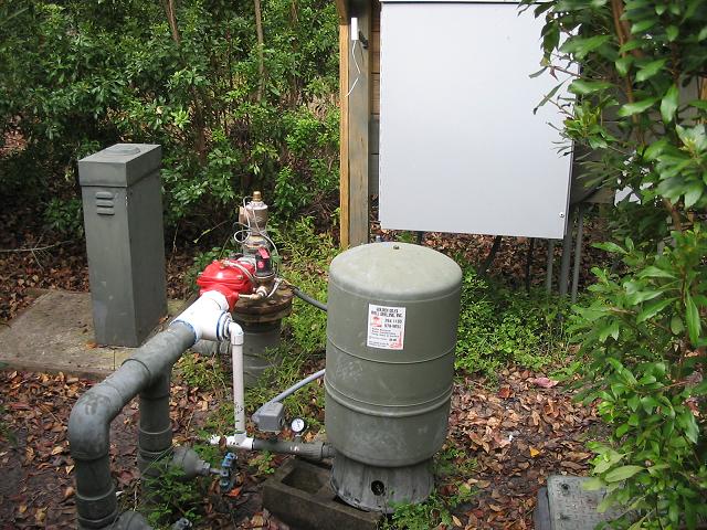
Thanks for the picture Ron.  No news is usually good news but, have you heard anything from the people at Wala Wala College about what they think about the performance of this system?

1547
Pumps, Wells, Tanks, Controls / Water Hammer on Community Water System
« on: February 04, 2007, 08:46:15 AM »
Hi Ron, thought I might chime in.  Very good explanation of how a CSV stops water hammer.  I have learned something recently.  You do not have to have the CSV set at the same pressure as the pressure switch ON setting to eliminate water hammer.  With a 60/80 pressure switch you could set the CSV for 70 PSI and the pump will still start at 5 GPM with no water hammer.  It seems that even though the CSV is set at 70 and the pump starts at 60, the CSV will still be in the closed to 5 GPM position when the pump starts.  It will not stay in this position for long but, will still absorb the shock wave as the pump starts, then quickly opens to allow full flow from the pump until pressure reaches 70 PSI.  The loading chamber or bonnet of the CSV will be full of water holding the valve closed when the pump starts.  As soon as the pump starts, the flow from the pump will begin to lift the diaphragm to an open position.  The diaphragm will still only open as fast as the water in the diaphragm chamber can be pushed out through the pilot valve and control tubing.  In other words, with the valve set at 70 using a 60/80 pressure switch, the valve will quickly open when the pump starts but, will still make the pump start at 5 GPM which eliminates water on pump start up.  The CSV must still be set lower than the OFF setting of the pressure switch to eliminate water hammer during pump shut off and also to allow the CSV to function.

1548
Pumps, Wells, Tanks, Controls / Pump for Heat Pump has high electric bill
« on: February 02, 2007, 09:00:17 PM »
If your pump is cycling 19 times an hour, then it is obviously a larger pump than it needs to be for the heat pump.  Changing to a smaller pump that will run continuously at the flow required will reduce the electric bill a little.  However, this could leave you out of water when the heat pump is running and you require water in the house at the same time.  You probably need the size of pump you have to use for the dual purposes of heat pump and house.  Cycling the pump 19 times per hour is the real problem.  Cycling destroys the pump system.  Replacing the pump system often can be so expensive that saving a little energy will become low on the list of priorities.  A Cycle Stop Valve in this situation may not save you any energy because, even though your pump is cycling now, it is still running at about it’s most efficient point.  A Cycle Stop Valve will push the pump out of it’s most efficient point by a little bit but, it will probably make that up by eliminating 19 starting spikes per hour.  What the Cycle Stop Valve will do however, is triple or quadruple the life of the pump system by eliminating all that cycling.  Instead of buying a new 1 HP pump every two or three years, eliminating the cycling will make one pump last 8 to 10 years or more.  Making your pump system last can quickly become more important than saving an extra $20.00 per month on the electric bill.

Even if the heat pump could save $250.00 per year, if your $1,000.00 pump will only last 4 years then you are not saving energy or money.. If you are really looking at energy savings alone, you may have to look back further. If saving a little energy means replacing a pump every 5 years instead of it lasting 20 years, then how much energy is used to manufacture, transport, install, and dispose of those extra pumps and motors. A big part of what you pay for the extra equipment, is used for energy. It is like the hybrid cars. If you have to replace the batteries every 35,000 miles, the money you save on gas is spent on batteries.  The cost of batteries includes the energy to mine, manufacture, and transport new batteries as well as everything that is involved in disposing of the old batteries. Making equipment last, is the best way to save money and energy.

You could us a ½ HP well pump that is throttled back very little with a valve to match the requirements of the heat pump.  Running at 20 PSI instead of 50 PSI this ½ HP pump would use less than half the energy you are using on the heat pump now.  Before the heat exchanger you can tee to a ½ or 3/4 HP jet pump with a CSV and a small bladder tank to feed 40/60 PSI pressure to the house. When the house needs water and the jet pump starts, the back pressure on the well  pump decreases and the well pump begins to supply more water feeding the heat pump and the jet pump for the house at the same time.   The jet pump will pick up water at 20 PSI and deliver the GPM needed for the house at a constant 50 PSI.  When the house is no longer using water, the small pressure tank fills to 60 PSI and the jet pump is shut off.  Then the back pressure on the well pump will increase, reducing the output of the well pump to supply the heat pump alone.  In this way you are only running a ½ HP pump instead of a 1 HP pump for the heat pump.  Then another ½ or 3/4 HP pump comes on only when needed to boost the flow and pressure to the house.  With a Cycle Stop Valve on both pumps, they will last a long time so this $40.00 per month energy savings from the heat pump will really be a bonus.

1549
Pumps, Wells, Tanks, Controls / Two Pumps in the same well
« on: February 02, 2007, 07:46:34 PM »
It seems simple when you see a picture and hear it explained so nicely, but a lot of thought goes into keeping it simple and making it work so beautifully.  My hats off to Jeff for making this work so well.  I hear the customer is happy and basically says he hasn’t had to give the water supply a second thought since start up of the system.  Maybe Jeff can get us a picture of the installation and possibly a few words from the operator or owner?  Good Job!

1550
Pumps, Wells, Tanks, Controls / Cycle Stop Valve used with a VFD
« on: February 01, 2007, 07:54:00 PM »
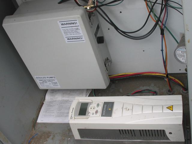
As long as the VFD will still run the motor at full speed, you can convert it to an electronic soft start.  With some Drives you can use the two wires from the pressure transducer directly on a standard pressure switch.  Other drives will have a place for two wires from a switch or pilot control and the transducer wires are just disconnected.  You will have to read the wiring diagram for the particular Drive to determine which two connections to make to a pressure switch.  Then if possible you want to program the Drive to ramp up within 2 to 3 seconds.  Install a Cycle Stop Valve on the discharge of the pump and tee off to a small bladder tank with the pressure switch as per normal Cycle Stop Valve instructions.  Adjusting the Cycle Stop Valve and pressure switch as per normal instructions will allow you to use from 5 GPM to 200 GPM and maintain 70 PSI.  The pressure switch adjustment can be according to the size of tank installed.  Normally a 60/80 pressure switch setting with about an 80 gallon tank will store 18 gallons for leaks and gives you almost 2 minutes of run time after all the sprinklers go off.  Later on when the drive completely fails you can easily switch over to a standard across the line starter or another soft start.  I find the old style Auto Transformer type soft start panels to be more reliable than electronic soft starters if you can find one.

1551
Pumps, Wells, Tanks, Controls / Well Driller needs help with 100 GPM pump
« on: January 29, 2007, 07:14:32 PM »
Excellent answer Porky!  Maybe he could just take off those 2 extra tanks and sell them on another job or keep them for spares.  If he doesn’t want to remove the tanks, the extra storage is not hurting anything and would save a few cycles for the home use.  To be able to leave all three tanks in line and not take so long for the pump to shut off, you can turn the CSV setting up closer to the off setting of the pressure switch. If he is getting 12 minutes run time with the CSV set at 50 and the pressure switch at 40/60 , then he will get 6 minutes run time if you set the CSV to 55 PSI, and a little over 3 minutes if the CSV is set at 57 PSI.  I wouldn’t go any closer to 60 than that because you have to leave a little time for the CSV to catch.  Set at 58 or 59 the pressure switch would probably bounce the pump off before the CSV has time to work.

1552
Pumps, Wells, Tanks, Controls / Pump Turns on and off too often
« on: January 24, 2007, 08:55:18 AM »
When you are running water you must use as much water as your pump will produce.  If you have a 20 GPM pump then you must always use 20 GPM.  If you are only using 10 GPM and your pump is producing 20 GPM, the other 10 GPM is going into the pressure tank until it reaches 60 PSI and the pressure switch shuts off the pump.  Then the 10 GPM that you are still using drains the tank from 60 PSI to 40 PSI and the pressure switch starts the pump again.  Your pump could be destroyed by pumping a lot of sand or might get hit by lightning but, most pumps are destroyed from excessive cycling on and off.  Pumps are made to run continuously and the worst thing you can do is let them cycle on and off.  If your pump is on for 2 minutes and off for 2 minutes then it can cycle 360 times every 24 hours or 131,400 times per year.  Submersible pumps and motors are only designed to last about 180,000 cycles.  The sooner you use up these 180,000 cycles, the sooner you are going to have to buy a new pump.  A Cycle Stop Valve knows how much water you are using and chokes back the flow from the pump to match the amount of water you are using.  If you are using 10 GPM then the CSV makes the pump produce only 10 GPM.  Then there is no extra water being produced to cause the tank to fill so cycling is eliminated.  A burned pressure switch is usually the first indication that your pump is cycling excessively.  To stop a pump from cycling excessively you either need to run enough water to use everything the pump will produce, install about four times as many pressure tanks as normal, or use a Cycle Stop Valve to continually vary the output of the pump to match the amount of water you are using.

For more info see these Links;
http://www.cyclestopvalves.com/video/commercial-dsl.wmv
http://cyclestopvalves.com/homeowners_3.html
http://cyclestopvalves.com/homeowners_1.html
http://cyclestopvalves.com/references_2.html

1553
Pumps, Wells, Tanks, Controls / Tank sizing
« on: January 23, 2007, 09:38:26 AM »
A Cycle Stop Valve or CSV makes the amount of flow coming from your pump exactly match the amount of flow you are using.  The CSV1 has a minimum flow of 1 GPM.  So as long as your shower or sprinklers are using at least 1 GPM,  The water comes directly from the pump, goes through the CSV at 50 PSI, and then right past the pressure tank to the sprinklers, shower, or where ever you are using water.  In other words, as long as you are using more than 1 GPM, water does not go into the tank so, the size of the tank is unimportant.  However, when you are not using any water, the 1 GPM that is still going through the CSV has no place left to go except the pressure tank.  The pressure tank is then slowly filled from 50 PSI to 60 PSI and the pressure switch shuts off the pump.  When the pump is off, you are able to use the water stored in the tank for ice makers, toilets, hand washing, and leaks before the pump will have to start up again.  This is when the size of the tank becomes important.  You do not want the pump to start up every time you flush a toilet or the ice maker fills.  So a tank that holds 5 gallons of water, which is about a 20 gallon actual size tank, will allow you to flush a 1.6 gallon toilet three times before the pump must restart.  Tanks smaller than 20 gallon size can be used but, you must make sure that even at the worst case scenario, the pump does not cycle on and off more times than the pump/motor manufacturer suggest.  With your size pump the manufacturer recommends no more than 100 starts per day.  We know the CSV will not allow the pump to cycle on and off at all as long as more than 1 GPM is being used so, the worst case would be a leaking faucet or running toilet that is using about ½ of a gallon per minute.  In this case when the pump starts at 40 PSI, the CSV150 will let the tank fill at full flow from the pump until pressure reaches 50 PSI.  Then the CSV closes down to 1 GPM.  ½ of this GPM is going to the leaking faucet and the other ½ of a GPM is filling the tank from 50 to 60 PSI.  The tank holds 5 gallons between 40 and 60 PSI so, it is half full at 50 PSI.  Filling the last half of the tank, which is 2.5 gallons, at ½ of a GPM will cause the pump to run for 5 minutes.  When the tank is filled to 60 PSI the pressure switch shuts off the pump.  Now there is still have ½ of a GPM leaking at the faucet so the 5 gallons in the tank will be drained in 10 minutes as the pressure drops from 60  to 40 PSI.  At 40 PSI the pressure switch starts the pump and the process is repeated as long as the faucet continues to leak.  5 minutes to fill the tank and 10 minutes to drain it is a cycle time of 15 minutes.  Doing the math you will see that there are 1440 minutes in a day.  1440 minutes divided by 15 minutes of cycle time leaves 96 cycles per day.  This is just under the 100 maximum starts per day recommended by the pump/motor manufacturer so 20 the gallon size tank is the smallest that should be used.  The less number of cycles on your pump, the longer your pump system will last.  Doubling the size of tank to 40 gallon size will cut the number of cycles in half from 96 to 48 per day.  Of course if you do not have any leaks in the system or do not have any water uses that are less than 1 GPM, a smaller tank will work fine.  Pump systems for irrigation only that are not attached to a house have much less chances for leaks and can use smaller tanks.  Smaller than 20 gallon size tanks can also be used for house systems as long as you do not have any leaks.  Cycle Stop Valves, Inc. always likes to assume worst case scenarios and therefore does not recommend smaller than a 20 gallon size tank with this valve.  Use the above information to decide what size tank you would like to use.  Also our tank size calculator makes it easy to figure your particular worst case scenario.  See these Links;
http://cyclestopvalves.com/runtime_app.php
http://cyclestopvalves.com/tanksizing_12.html


1554
Pumps, Wells, Tanks, Controls / Homeowner VFD or CSV
« on: January 23, 2007, 08:11:13 AM »
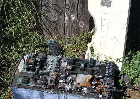
Recently they made everyone send back their Goulds Balance Flow controllers to get a new computer chip installed. So the ones they are selling now have less than a year track record.  Only time will tell if any of these will still be working in five years.  Buy a three phase motor, and decide you don't like the variable speed controller, now you have to buy a new single phase motor. 4.5 gallon tank actually holds about a gallon of water, pump has to come on every time you flush a toilet. The most recent problem I am hearing from installers is that when the sprinkler system comes on, the one gallon in the tank is gone in seconds, the BF controller has a slow start so it takes a while for the sprinklers to start squirting. Mean time the bladder in the tank has bottomed out, pressure is low, pipes start shaking and rattling, lot of noise heard in the house. One installer said he has to strap all the pipes down to the floor or walls just to keep them from breaking.  Other Variable Speed Pumps on the market also react slowly causing the same problem.   Variable frequency controllers send out a radio signal that blocks AM radio, cell phones, and causes static lines on you TV. This radio signal that escapes is called stray voltage. They are just finding out that this stray voltage is causing dairy cattle to get sick and produce 20 to 30% less milk.  A VFD is a computer that controls your pump. How dependable do you think you water supply would be using computerized controls? Use a standard pump, little larger pressure tank (20 gal size holds 5 gallons of water), single phase motor and control, and a Cycle Stop Valve to provide the constant pressure. Simple controls make dependable pump systems. Nothing is more annoying than waking up to no water coming out of the faucet.

The harmonics from a VFD are fed back into the electric grid. If you have a VFD with 6 switch operations, then all harmonics not divisible by 6 (7th, 9th,11th, 13th, etc.) are forced back into the incoming power supply. I am sure the VFD machine itself can broadcast radio frequencies but, the harmonics fed back into the power supply can use the incoming power wires as an antenna. Most insulated electric wire in a house has 600 Volt insulation. A 240 volt VFD produces voltage spikes of up to 1000 volts and a 480 volt drive produces spikes of 2000 volts. Your 600 volt insulated wires can't hold back these 1000 volt spikes and they leak out anywhere they can. Also you would have to use wires that have metal or copper shields properly grounded around them to hold in the radio frequencies. Otherwise any or every wire in or around your home can be transmitting radio frequencies from the VFD. Why else would AM radios stop working when you just get close to the area? Your neighbors VFD could actually be affecting you. I also disagree that the motor will last because it can't tolerate the 1000 volt spikes from the VFD for very long. Not to mention that reducing the speed of the pump/motor causes it to go through the mechanical frequency of every component in the pump/motor. At standard 3450 RPM these mechanical frequencies have been balanced out. But at 3120 RPM the motor shaft vibrates. At 3266 RPM the laminations in the motor vibrate. At 3289 RPM the impeller vibrates and so on. Its really calledresonance but, it is still a vibration.Its like driving a car with one unbalanced tire. Even though the tire is what is unbalanced it shakes the whole car and eventually the car starts falling apart. Then there is the "skin effect". Radio frequencies, which is what the motor runs on when using a VFD, travel on the skin of wire unlike regular AC voltage which travels in the core of the wire. When this radio frequency leaks out of the wiring it then travels on the skin of the equipment such as steel pipe and fittings, pump and motor casings, etc. It causes damage that looks like electrolysis, which is the soft particles in the metal dissolving into the water. Then there is the excess heat buildup in the motor from operating on harmonic frequencies and EDM currents that require motor shafts to be grounded to prevent bearing failure. I could go on with other negative side effects of the VFD. We stopped using VFD's in 1992. We realized back then that anything we did to help solve these problems was just a band aid. The root of these problems can't be fixed unless you can change the laws of nature. We built the Cycle Stop Valve in 1993 to simulate the control of a VFD without causing all the negative side effects of VFD. It turned out to be a very simple thing to do. When we realized that we got the same power reduction by using a valve to control a normal full speed pump as they get when slowing the RPM with a VFD, everything else was just icing on the cake. No matter how they try to tell you that the VFD is the most advanced technology, the Cycle Stop Valve is newer and more advanced because it can do more with less.
http://cyclestopvalves.com/comparisons_13.html
http://cyclestopvalves.com/comparisons_5.html
http://www.cyclestopvalves.com/video/conserving_water-dsl.wmv


1555
Pumps, Wells, Tanks, Controls / air injector
« on: January 22, 2007, 05:01:13 PM »
An air injector utilizing a venturi nozzle is used to add air to a water system to remove Sulfur, H2S, or other smelly substances.  A standard air over water galvanized type pressure tank is used, instead of a bladder tank, to allow the air to mix with the water.  A float operated Air Volume Control installed ½ way on the side of the tank releases any excess air to prevent the air from entering the pipe lines or house.  A venturi air injector needs a certain amount of flow to produce the pressure differential across the venturi that draws in the air.  When used with a Cycle Stop Valve, the flow being used determines the flow coming through the venturi.  If a low flow rate such as 1 to 5 GPM is being used for long periods of time, the venturi will not draw air.  When large enough flow rates are being used, the venturi draws in air as usual.  When water is used intermittently as for use in the home, it is important that most of the water stored in the pressure tank be mixed with the correct amount of air.  When the pressure increases to the setting of the Cycle Stop Valve, the flow is reduced to 1 GPM, which is not enough to allow the venturi to draw in air.  Therefore, the setting of the Cycle Stop Valve should be as close as possible to the off pressure of the pressure switch.  In other words, if you have a 60 PSI Cycle Stop Valve, the pressure switch setting needs to be about 43/63.  In this way the tank is filled at the maximum rate the pump can produce, and the air injector is working until the pressure reaches 60 PSI.  Most of the tank is then filled with water and mixed with air, and only the last couple of gallons of water will enter the tank without air as the CSV reduces the flow rate to 1 GPM.   Above 60 PSI the flow rate is too low for the venturi to function but, the tank is already almost full and the pressure switch quickly shuts the pump off at 63 PSI and leaves plenty of air in the tank.

Pages: 1 ... 102 103 [104]